Problem Statement
Objectives
The primary objective of the project is to determine the bending stiffness properties of the cable that are driven by the unique geometry and composition of the cable array. As previously stated, bending stiffness refers to a material’s resistance to bending deformations under an external force. This property is characterized by the material’s Young’s modulus and the structural second moment of inertia of the cross-section. To begin, the cable array is composed of copper stranding and polytetrafluoroethylene, or PTFE, insulation. Although copper is a widely used and understood material, the stranded layout creates complications in the bending properties due to friction between the strands. Additionally, the anisotropic nature of PTFE creates further challenges in the ability to approximate the bending stiffness. With all this in mind, the project scope was to determine the best experimental method to measure the bending stiffness or bending modulus.
Specifications and Requirements
A cable array with dimensions 600 × 115 × 4 mm is attached to a moving plate that is accelerated up to 313 m/s², causing the cable to deform unexpectedly and experience friction with the surroundings. Over time, this friction causes wear and tear on the cable, ejecting particulates into the system and potentially contaminating the product. These issues would increase the frequency of maintenance and repairs, increasing cost and lowering reliability. As a result, the client has requested a thorough investigation of the cable array and its structural properties. They hope to use the data to develop an improved cable design and prevent these issues from arising.
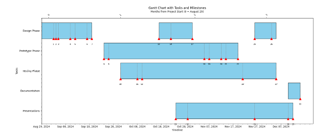
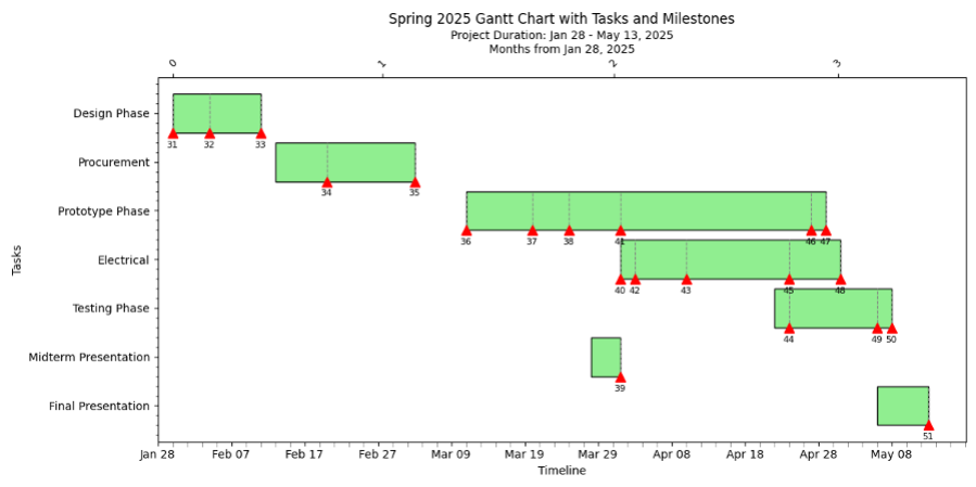
Steps Taken
To determine the cable properties, the team began their work by recreating the cable in SolidWorks. Next, the team focused on researching existing literature on cables and the methodology used to test them. After some examinations, we decided to use the standard 4-point bend test as the static design. Using the CAD model, we ran preliminary simulations to obtain stress, displacement, and ultimately the bending modulus using the 4-point bend test. Then, we conducted an identical experiment using the physical cable and 3D printed parts that served as the support and loading arms. After running a couple of trials, we plotted the stress vs. strain curves and obtained the bending modulus. Then, the focus shifted to a dynamic design approach. Using previously acquired knowledge regarding the various setups, we developed a dynamic test stand after several design iterations. Lastly, we manufactured the dynamic test stand, conducted measurement experiments, collected the data, and compared it with the data from the static test stand.