Design Iteration 1
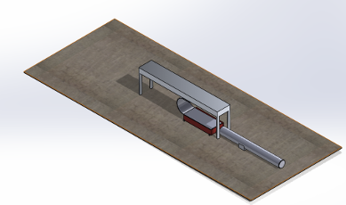
Our initial design concept was developed based on the core principles discussed for the dynamic testing setup. In this approach, the cable is pre-bent to match a vertical plate-to-plate spacing of 150 mm and is securely clamped at both ends, fixed at the top plate and attached to a movable base at the bottom. The key objective of this setup is to measure the force exerted by the cable on the fixed top plate. To achieve this, a force sensor is incorporated at the top, which continuously captures data throughout the testing process. Continuous data output is essential due to the dynamic nature of the test, where the bottom base moves back and forth to simulate real operating conditions similar to those inside ASML’s lithography machines.
The motion of the bottom base is achieved using a linear actuator, which drives the platform to oscillate horizontally, fully extending and contracting the 600 mm cable. To allow for this, the bottom base must move at least 300 mm from its starting position. This displacement ensures the cable undergoes its full range of motion, enabling comprehensive analysis of the forces it generates during operation. The base is mounted on four small wheels to allow horizontal motion; however, this introduces a significant design limitation: the absence of guide rails or linear guides. Without a guiding mechanism, the base’s movement may deviate from a true linear path, potentially leading to inaccurate test results or inconsistent loading on the cable. Another major drawback is the requirement for a relatively large linear actuator. Achieving the necessary 300 mm travel at a high speed demands a powerful actuator, which significantly increases the size and weight of the overall system. This conflicts with one of our primary design goals: to keep the test stand as compact and efficient as possible. The large actuator also influences the test fixture’s footprint and potentially complicates the integration of other components.
Despite its limitations, this initial concept was highly valuable in shaping our understanding of the project’s scope. It highlighted several critical areas for improvement, such as the need for precise guidance mechanisms for the moving base and more space-efficient actuation solutions. Going forward, many components from this design, such as the use of a linear actuator for controlled motion and the force sensor placement, will be retained and refined. The insights gained from this concept will directly inform the next iterations of the test fixture, ensuring they are both functionally robust and aligned with the company’s expectations for performance and form factor.
Design Iteration 2
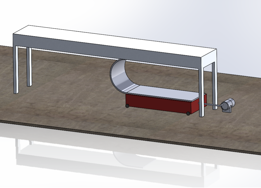
The design for this test setup aims to measure the force exerted by a cable on a fixed stand by coordinating several mechanical components. At the top, a fixed plate securely holds the upper end of the cable, establishing a stable anchor point. The bottom end of the cable is attached to a movable base mounted on wheels, allowing for horizontal movement. This base is actuated by a DC motor, which drives a connecting rod to convert rotational motion into linear motion. As the motor shaft rotates, the connecting rod pushes and pulls the base, simulating the dynamic motion experienced by cables in operational environments. A force sensor is strategically placed between the fixed stand and the cable to continuously capture the force exerted as the cable flexes and straightens during the test cycle. The cable is pre-bent, and as the movable base travels up to 300 mm, the cable undergoes significant bending, at times striking the sensor and fixed stand, creating the measurable force that the sensor records.
However, this design faces two significant drawbacks. First, the displacement of the base is inherently limited by the geometry of the motor shaft and the mechanics of the connecting rod. Given the motor shaft’s radius of just 0.056 mm, each full rotation only generates 0.056 mm of linear movement at the base, an amount far too small to meet the 300 mm travel requirement. To overcome this, we considered attaching a large rotating disk to the motor, with the connecting rod mounted at the edge of the disk to amplify the motion. For 300 mm of displacement, a disk with a 150 mm radius would be required. While this modification increases the effective range of movement, it introduces new complications: the size of the disk could interfere with the fixed top plate, the connecting rod’s swing path may create clearance issues, and the overall test stand footprint would increase significantly, contradicting our aim to keep the setup compact and manageable.
The second critical issue involves the stability of the movable base. Because the base is mounted on wheels without any guiding mechanism, there’s a high risk of lateral swerving during operation. This side-to-side motion compromises the linearity of the displacement, introducing variability in the cable’s loading and affecting the accuracy of the force measurements. Without guide rails or grooves to constrain the motion path, the system lacks the precision necessary for repeatable and reliable testing.
In summary, while this concept offers a creative mechanical solution using a DC motor and connecting rod to simulate dynamic motion, it is hindered by limitations in displacement capacity and motion accuracy. These challenges highlight the need for design refinements, such as implementing a more suitable actuation method and adding guidance systems to ensure true linear movement, both of which are essential for achieving the desired test performance.
Design Iteration 3
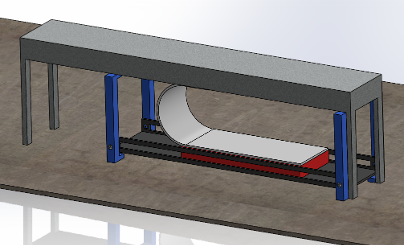
This revised design maintains the essential components of the previous setups, namely, the fixed top plate, movable base, cable, and force sensor, but introduces a new motion system centered around a stepper motor and a significantly redesigned movable base. Rather than relying on a connecting rod powered by a standard electric motor, the system now utilizes a stepper motor to deliver precise, incremental displacement. This provides significantly improved control over the motion profile, allowing for more accurate and repeatable cable testing. The movable base is no longer mounted on wheels; instead, it is built as a rectangular structure that slides along a pair of linear guide rails. These guide rails ensure strictly linear motion, eliminating the lateral swerving issues encountered in previous designs and significantly improving the consistency of the force measurement.
The platform supporting the movable base is elevated and rigidly fastened to the legs of the fixed table using screws, carefully preserving a vertical plate-to-plate spacing of 150 mm. This spacing is critical for maintaining the intended cable geometry during testing, ensuring that the cable is bent consistently and that the force sensor readings reflect true mechanical behavior. Linear displacement is achieved through a modified actuator mechanism, consisting of a threaded rod coupled to the stepper motor. As the motor rotates, the nut traverses along the threaded shaft, converting the rotational input into linear motion. The rod itself is precisely 300 mm long, enabling the base to move across the entire required displacement range, which in turn induces the full bending profile in the 600 mm cable. This range is essential to replicate the extreme dynamic conditions that the cable would face in real-world applications.
However, this approach introduces some trade-offs. One of the main drawbacks is that the use of a threaded rod inherently limits speed and introduces less precise motion compared to other linear actuation methods. Threaded drives tend to have backlash and are generally slower due to the mechanical friction and the finer pitch required for controlled motion. Additionally, while the guide rails improve accuracy by constraining the motion path, they may also introduce unwanted friction, especially if not properly lubricated or aligned. This additional resistance could affect the responsiveness of the system and place extra load on the stepper motor, which must be accounted for during component selection.
Despite these limitations, the advantages of this design are substantial. The use of a stepper motor allows for fine-tuned displacement control, while the guide rails provide structural stability and motion linearity. The modular nature of the design also means that the size and length of the system can be modified to accommodate different cable types or test scenarios. Overall, this configuration addresses the major shortcomings of earlier concepts, particularly motion inaccuracy and instability, while offering a more scalable and precise testing solution.
Design Iteration 4
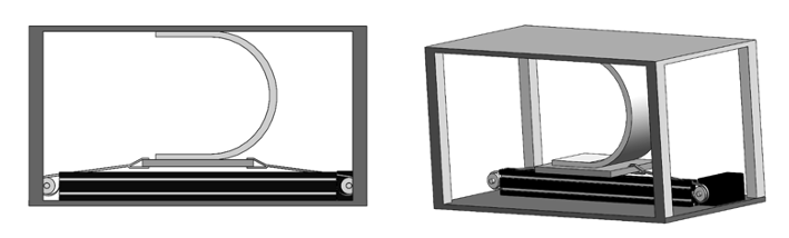
This design iteration builds upon the strengths of the previous concepts by introducing a belt-driven linear actuator housed within a box-type enclosure. It retains the use of the stepper motor from Design 3, leveraging its precise incremental control to manage displacement with high accuracy and repeatability. The belt-driven system provides a notable improvement in speed and smoothness of motion compared to the threaded rod used previously, allowing the movable base to traverse the full 300 mm range more efficiently. To maintain linearity and eliminate any lateral deviation during motion, the design incorporates a guide rail system, which ensures that the base moves in a straight and stable path. This setup directly addresses the key shortcomings of earlier designs, specifically, the motion instability caused by wheel-based platforms and the limited displacement capacity of connecting rod or threaded mechanisms.
Encasing the entire actuation assembly in a rigid, box-type structure adds structural integrity and protects the internal components from dust, debris, or mechanical interference, which is particularly important in precision testing environments. The belt mechanism also helps reduce friction and mechanical backlash, leading to smoother, quieter operation, an important factor when running repeated or high-speed test cycles. Furthermore, this design enables greater control over test parameters, including speed, acceleration, and positional accuracy, offering enhanced flexibility for various testing protocols. By integrating these elements, the design not only improves the reliability and consistency of force measurements but also provides a more refined and scalable platform for dynamic cable testing, aligning closely with the performance and precision requirements of the company’s application.
Evaluation of Iterations
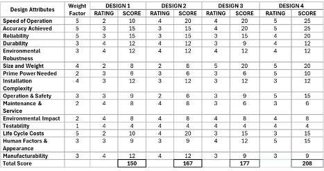
For this portion of our report, we will be evaluating every design mentioned in the previous section to determine the best design concept for our project. This evaluation works based on rating each design on some design attributes. These attributes are given a weight factor which is multiplied by the rating to obtain a score. The scores for each design attribute are totaled per design concept and compared at the end to determine the best design based on these attributes. The weight factors and ratings are chosen between 1 and 5, with 5 being the highest obtainable rating.
The attributes we will be considering for this project are as follows. We will also include a short description for each attribute to highlight what we feel are the important factors.
Design Attributes:
- Speed of Operation:
For this attribute, we will be considering the speed at which we will be able to obtain our results. We will also consider the speed of the test as well, meaning that if a concept is working with a slower motor for the motion of the base, it will receive a lower rating. - Accuracy Achieved:
For this attribute, we will be considering the accuracy of the result output by the test stand. In our case, we will be basing this on the Force reading provided, and any potential errors which may occur during our measurements. - Reliability:
For this attribute, we will be considering the overall consistency of the design concept. We want our test stand to repeatedly perform in the same way under the same conditions. In addition to this, we will also consider any possible malfunctions in the design. - Durability:
For this attribute, we will be considering the durability of the design concept. This means that we will consider the potential failure points of each design and base our rating on this. - Environmental Robustness:
For this attribute, we will be considering the overall robustness or strength of our design. We want our test stand to be able to work in almost any environment but acknowledge that this might be difficult especially since we are using many moving components which can degrade when used in certain environments. An example would be the usage of guide rails in dusty environments which can cause irregularities in the movement of a component. - Size and Weight:
For this attribute, we will be considering the overall footprint of the test stand. In our case the weight of the stand would be relatively similar across all of our designs, thus we will be focusing on rating our designs based on their compactness. - Prime Power Needed:
For this attribute, we will be considering the amount of power required to run our tests. The major components requiring power are the motors or actuators moving the base. - Installation Complexity:
For this attribute, we will be considering the effort required to set up the test stand and start acquiring results. All of our designs require the cable to be added manually, but some need additional setup in the case of an adjustable plate-to-plate distance. - Operation & Safety:
For this attribute, we will be considering the overall safety of the design. For this project, the idea is to encase every design with either clear acrylic or plastic to ensure safety. Thus, we can expect similar ratings for all designs for this attribute. - Maintenance & Service:
For this attribute, we will be considering the amount of maintenance required to keep the design running smoothly. We will consider designs with more moving components to require more maintenance, as these are more prone to failure. - Environmental Impact:
For this attribute, we will be considering the negative impact each design has on the environment. In our case all of our designs are pretty similar in that regard, all only run on electricity resulting in minimal pollution compared to an engine running on gasoline. - Testability:
For this attribute, we will be considering the effectiveness of each design to be tested for any issues or faults. In this case, as our designs are similar to each other, we will be taking into account the number of components that need to be tested for any faults/issues. - Life Cycle Costs:
For this attribute, we will be considering the overall cost to build and maintain each design. In our case, we can expect to focus on the initial costs of purchasing the motors or actuators and any other main components. - Human Factors & Appearance:
For this attribute, we will be considering the overall look of the design. As this is subjective to everyone we decided to focus on the size/overall footprint of each design. We are keeping in mind that every design will be encased in clear acrylic or plastic and will consider this in our ratings. - Manufacturability:
For this last attribute, we will be considering the manufacturability of each design. We will keep in mind the complexity and the amount of work required to assemble each design.
Final Design Choice
Having thoroughly analyzed and discussed each design iteration and its key attributes, we are now in a position to evaluate and rank the concepts based on a set of defined performance criteria. After scoring each design against parameters such as accuracy, reliability, speed, manufacturability, and overall feasibility, Design 4 emerged as the most effective solution, achieving a total score of 208. This places it 31 points ahead of the next closest competitor, Design 3, indicating a clear performance advantage.
Design 4 excelled particularly in the categories of Speed of Operation, Accuracy, and Compactness, factors that are critical to our test setup’s intended functionality and integration within the broader system environment. The use of a belt-driven linear actuator and a stepper motor provided smoother and faster motion compared to previous designs, while the inclusion of guide rails ensured consistent linear displacement with minimal deviation. Additionally, the enclosed box-type structure contributed to a more refined, space-efficient footprint, which is essential for test environments with limited space and high cleanliness standards.
In terms of Reliability, Durability, Testability, and Manufacturability, Design 4 performed consistently well, matching or slightly exceeding the other concepts. Its modular layout and enclosed components contribute to easier maintenance and protection from environmental factors, enhancing long-term reliability. Furthermore, its straightforward mechanical assembly and standardized components improve manufacturability and reduce potential issues during production or testing. Overall, Design 4 represents a well-balanced solution that successfully addresses the shortcomings of previous iterations while meeting the company’s operational and engineering standards.